- 您现在的位置:买卖IC网 > Sheet目录321 > DM163035 (Microchip Technology)KIT DEVELOPMENT PICDEM LAB
�� �
�
�Comparator� Peripheral� Labs�
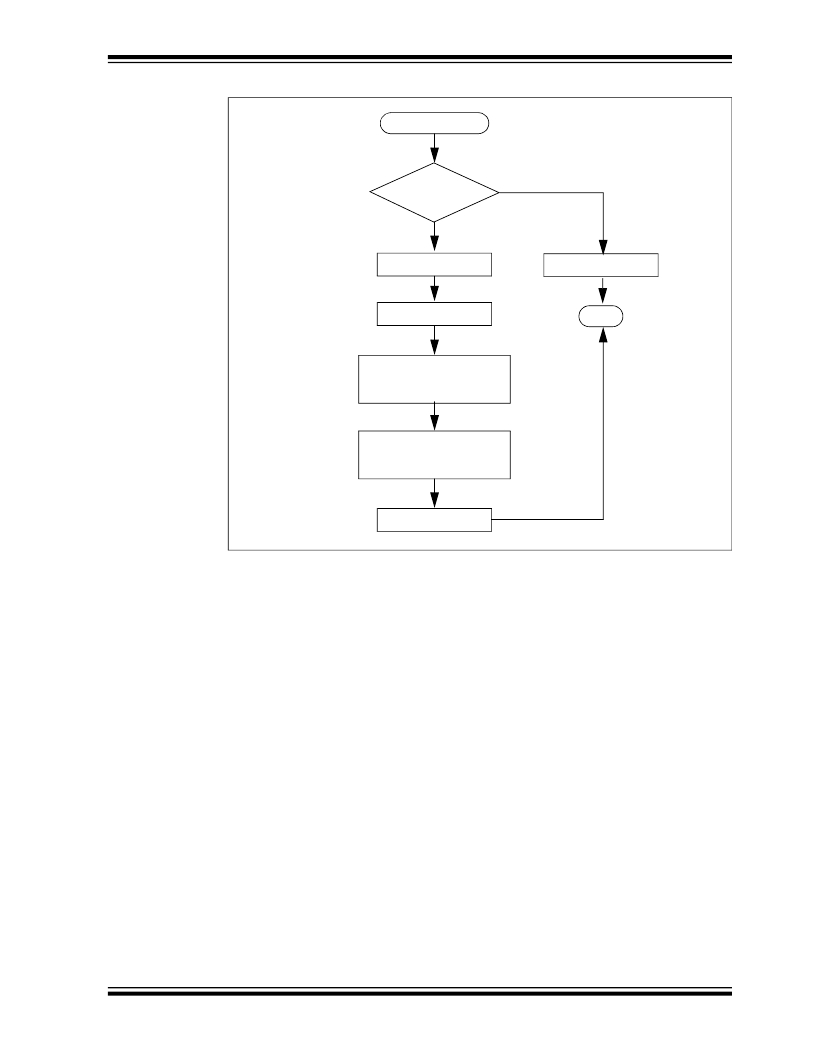
�FIGURE� 4-7:�
�TMR0_ISR� FLOWCHART� FOR� COMPARATOR� LAB� 3�
�TMR0_ISR()�
�T0IF� =� 1�
�?�
�YES�
�Clear� T0IF� Flag�
�Turn� off� Timer1�
�NO�
�Keep� PORTC� the� same�
�END�
�Assign� PORTC� the� T1MRH� value�
�shifted� 4� bits� to� the� right�
�Clear� the� Timer1� result� register�
�pair� TMR1H:TMR1L�
�Turn� on� Timer1�
�The� TMR0_ISR()� first� checks� if� a� Timer0� interrupt� has� occurred� (good� programming�
�practice).� If� so,� then� the� Timer0� interrupt� flag� is� cleared� and� Timer1� is� turned� off� to� stop�
�counting� the� oscillator� clock� pulses� on� the� T1CKI� pin.� Next,� the� 4� MSbs� of� the� Timer1�
�16-bit� result� is� assigned� to� the� RC0,� RC1,� RC2� and� RC3� pins� to� light� the� associated�
�LEDs.� Finally,� the� Timer1� result� register� pair� are� cleared� and� Timer1� is� turned� on� to�
�begin� a� new� count.�
�4.2.6.3�
�PROCEDURE�
�Using� the� firmware� developed� in� the� previous� lab,� make� the� following� changes:�
�1.� Copy/paste� the� code� in� Example� 4-4� into� the� top� of� the� main� firmware� source� file�
�under� the� heading� labeled:�
�//----------------INTERRUPT� CODE---------------�
�?� 2009� Microchip� Technology� Inc.�
�DS41369A-page� 71�
�发布紧急采购,3分钟左右您将得到回复。
相关PDF资料
DM164120-1
BOARD DEMO PICKIT 2 LP COUNT
DM164120-3
BOARD DEMO PICKIT2 28-PIN
DM164120-5
BOARD DEMO PICKIT 2 64/80-PIN
DM164123
KIT MANAGEMENT SYSTEM PICDEM
DM180021
KIT STARTER MPLAB FOR PIC18F MCU
DM183022
BOARD DEMO PIC18FXX22 64/80TQFP
DM183032
BOARD EXPLORER PICDEM PIC18
DM240001
BOARD DEMO PIC24/DSPIC33/PIC32
相关代理商/技术参数
DM163035+TEFLCST3
制造商:Microchip Technology Inc 功能描述:KIT PICDEMLAB+FLOWCODE-HOME BUNDLE/ 制造商:Microchip Technology Inc 功能描述:PICDEM, FLOW CODE, LAB, DEV KIT
DM163045
功能描述:开发板和工具包 - PIC / DSPIC PICDEM Lab Dev Kit (with PICkit 3) RoHS:否 制造商:Microchip Technology 产品:Starter Kits 工具用于评估:chipKIT 核心:Uno32 接口类型: 工作电源电压:
DM1-63-C
功能描述:端子 Metric Fem Disc non-insulated
RoHS:否 制造商:AVX 产品:Junction Box - Wire to Wire 系列:9826 线规:26-18 接线柱/接头大小: 绝缘: 颜色:Red 型式:Female 触点电镀:Tin over Nickel 触点材料:Beryllium Copper, Phosphor Bronze 端接类型:Crimp
DM1-63M-C
功能描述:端子 Metric Male Disc non-insulated, 0
RoHS:否 制造商:AVX 产品:Junction Box - Wire to Wire 系列:9826 线规:26-18 接线柱/接头大小: 绝缘: 颜色:Red 型式:Female 触点电镀:Tin over Nickel 触点材料:Beryllium Copper, Phosphor Bronze 端接类型:Crimp
DM164
制造商:SITI 制造商全称:SITI 功能描述:8x3-CHANNEL CONSTANT CURRENT LED DRIVER
DM1640
制造商:SANYO 制造商全称:Sanyo Semicon Device 功能描述:16 characters x 4 line Liquid Crystal Dot Matrix Display Module
DM1640-0AL1
制造商:未知厂家 制造商全称:未知厂家 功能描述:Optoelectronic
DM1640-0BL1
制造商:未知厂家 制造商全称:未知厂家 功能描述:Optoelectronic